Carbon-Di-Oxide Generation and Graphs

Carbon dioxide is generated in the top compartment. A vinegar dripper is inserted on top of baking soda. As discussed earlier baking soda and vinegar will generate CO2.

The PVC pipe has holes in it which will be a vent passage to CO2.  I used MQ-135 Sensor for Identifying the presence of CO2. The Data is generated and the graph is visualized using Matlab.

The Graph of CO2  shows that in the beginning  the CO2 ppm is around 32 and it got raised to 450ppm due to over dripping but gradually the dripping slowed down to 2 min per ml. Hence the graph became constant at 170-175 ppm.

CO2 in PPM  vs Time in Sec


Accelerator Graphs using motor

  1. Accelerometer on X-axis while using Motor

2. Accelerometer on Y-axis while using Motor

3.  Accelerometer on Z-axis while using Motor


4. Comparision of X,Y,Z  Axis


Schematics of sensors

  1. Breadboard diagram L298N


2. Breadboard diagram l298n for solenoid

3.  Motor Schematic diagram

4.  Solenoid Schematic diagram

5. MPU 6050 Solenoid

6.  TMP 36 diagram

7.  Tmp 36 schematics


Solenoid: Heat Vs Power Consumption

Solenoid: Heat Vs Power Consumption

The solenoid vibration unit was heating up extensively in our previous experiments. To understand the vibrations the data was generated. TMP36 was used in this process to collect temperature data of the solenoid.

The temperature of the solenoid varies with changing amperes, the following graph shows the change in temperature with respect to current.


Solenoids are not working below 0.7 amps. So, I opted 0.7 to be the least current input. But the problem is that the vibrations are not as strong as expected in at this rating.


To avoid this, we are using the PWM technique to control the solenoid at a minimum temperature. First, the solenoid was operated by increasing the duty cycle. The graph below shows the variation of the temperature in the solenoid, The graphs increasing duty-cycle is heating up just like the above graph.


Therefore, a constant PWM pulse is used, but the graph shows pretty good results, at 10Hz and 60Hz, The solenoid was not operating above 60Hz of frequency. Power Consumption graph is also generated. Duty cycle 100% and duty Cycle at 90% are tested to see which one give an optimum result. It shows that both are doing pretty good results in terms of heat generation.

Conclusion: Heat was a problem when the solenoid was used but that can be solved by using PWM pulse duty cycle at 100 at 50Hz to have minimum heat dissipation.

Vibration Unit

Motor Vibration

As discussed in our previous posts vibration unit has two main ideas as mentioned below. Both the experiments are conducted and the results are quite promising for the usage.

  1. One is to use an irregular load on the motor.
  2. The second is to use a linear actuator or a solenoid.

The idea was to create vibrations by adding unbalanced weights to the motor output. A metal clamp was connected to it which was acting as an unbalanced load. The motor input was connected to the 110V  AC to 12V  DC converter.  Check the video below


12V operated 330 rpm DC motors are used which is connected parallelly to the input power. This is a brief prototype to show how vibrations are generated.  To this model,  we can add motor drivers to make it automated.

Linear Actuator

This was the second idea to generate vibrations in our bot. We are using a linear solenoid movement to generate bang vibrations. Four 20N solenoids are used for this case which generates 80N  force of impact on the surface of the bot. These solenoids are connected parallelly to the 12V output. The working of the solenoid model is given below

Conclusion:

  1. The motor is creating higher vibrations compared to solenoids but the noise is also higher. But noise got significantly cancelled after placing a plastic doom over it. I think since the vibration unit is undergrounded it shouldn’t be a problem.

2. The solenoids create less sound but create more impact.  I think these perfectly mimic the animal’s movement.

Future scope

  1. Planning to add control drivers to the system.


******The content on this site is intellectual property. Action will be taken if this work published or copied without our permission. For more details contact Dr Michael von Fricken or Dr.Nathalia Peixoto******


Stationary Tick-Bot

TREMoR Design

What is TREMoR?

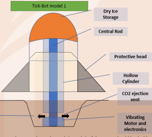
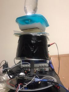
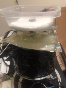
‘TREMoR’ (Tick collecting Robot for Entomological Modeling Research) is a stationary prototype device that builds on the standard tick trap approach to lure ticks. The Stationary Tickbot is undergrounded 1/6th of the meter. It consists of a compartment for dry ice which dispels CO2 and a motor which generates vibrations. This is done to mimic a living creature in the woods.  Dry Ice also keeps pumping fog (condensed water vapour). This will keep the surroundings of the bot moist an ideal environment for ticks. The collecting chamber is undergrounded. This keeps the ticks intact without escaping. The Design is explained below:


Storage System:

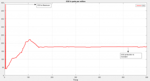
Dry Ice is a solid Carbon dioxide at a temperature of -79 degree Celcius. Dry Ice is stored and, and Corban di Oxide is passed from the flow path. The Co2 is invisible but the foggy substance is the water vapour condensing in the air.

The other two good approaches for generating CO2 are by using Yeast Fermentation process and also Baking soda and Vinegar Reaction. In this, the first approach produces water in the reaction which helps the surroundings of the bot to be moist.

CO2 Generation using Baking soda:  NaHCO3 + CH3COOH --> CH3COONa + H2CO3... and then H2CO3 --> H2O + CO2
Co2 generation using  Yeast Fermentation:  C6H12O6 → 2 C2H5OH + 2 CO.
CO2 generation by Baking soda and Calcium  Chloride: 2 NaHCO3 + CaCl2  CaCO3 + CO2 + 2 NaCl + H2O

The drawback in the second equation is that it won’t generate water molecules but the advantages are that it produces a good amount of CO2. The above four methods will be researched and the best and optimum method will be chosen for the project.


Collecting unit:

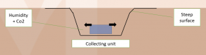
The Collecting unit can be designed in two ways. The first process is by collecting live ticks. The second process is by collecting the dead ticks. In the above design, ticks cannot escape the pit trap and would also not leave the place because of its suitable habitat.

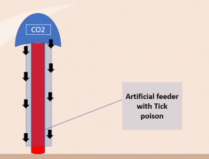
The second method is capturing the dead Ticks. This can be done by developing an artificial feeder. It is an artificial membrane made up of silicon. It is used as blood-feeders in the research laboratories. We can use the same technology to bait our ticks with a tick poison. Since the Poison is inside the bot the tick is exposed only when it bites the feeder.  This helps solves the purpose of not exposing poisonous chemicals into the environment.
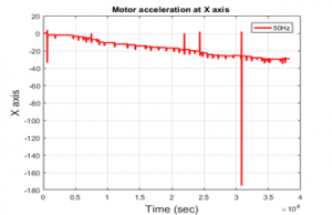
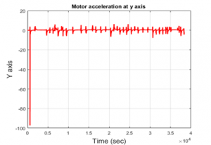
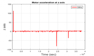

Ground Vibration:

The Idea of ground Vibration is to mimic the animal footsteps. This will lure the ticks as the can feel the vibrations of the animal movement. The ground vibration could be achieved in two ways:

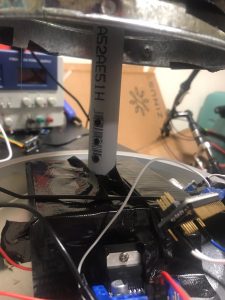
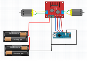
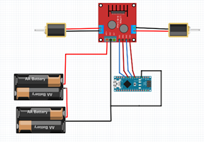
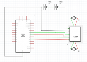
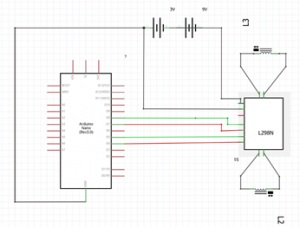
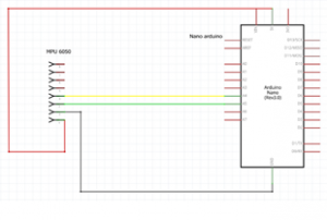
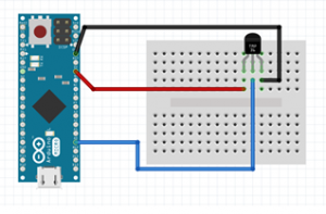
The dynamic motion of the motor:  This can be generated by small motors with high RPM.  This is to be done by placing a 12V motor inside the vibrating chamber. The vibrations must be made periodic by controlling the voltage of the motor. A simple example is our mobile phones in the vibrating state. Our mobiles vibrate with the help of a small motor. So, a powerful 12V high RPM must be good enough for the project. This can be done by a few simple electronics that are given :

  1. 12V motor
  2.   Pololu Driver 8835
  3. Arduino Nano or Raspberry
  4. Connecting wires

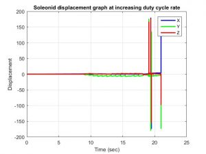
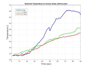
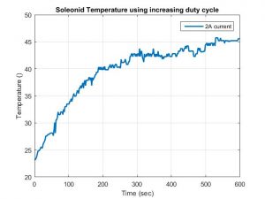
Oscillation of the Magnets: 

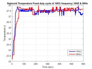
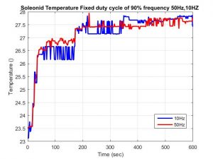
The oscillating solenoid is a good way to generate ground vibrations. This can be done by placing a magnet in between the solenoid. When current flows through the coil, it generates a magnetic field inside the coil which attracts the armature towards the centre of the solenoid using the same basic principles as ordinary electromagnets.

Image result for solenoid 20n datasheet

Since the armature is drawn towards the centre of the solenoid regardless of the polarity of the current, an opposing force is needed to return the armature into the starting position when the coil is not energized. This is achieved by using a spring mechanism. This movement can be converted into ground vibrations.

******The content on this site is intellectual property. Action will be taken if this work published or copied without our permission. For more details contact Dr Michael von Fricken or Dr.Nathalia Peixoto******